yapCAD
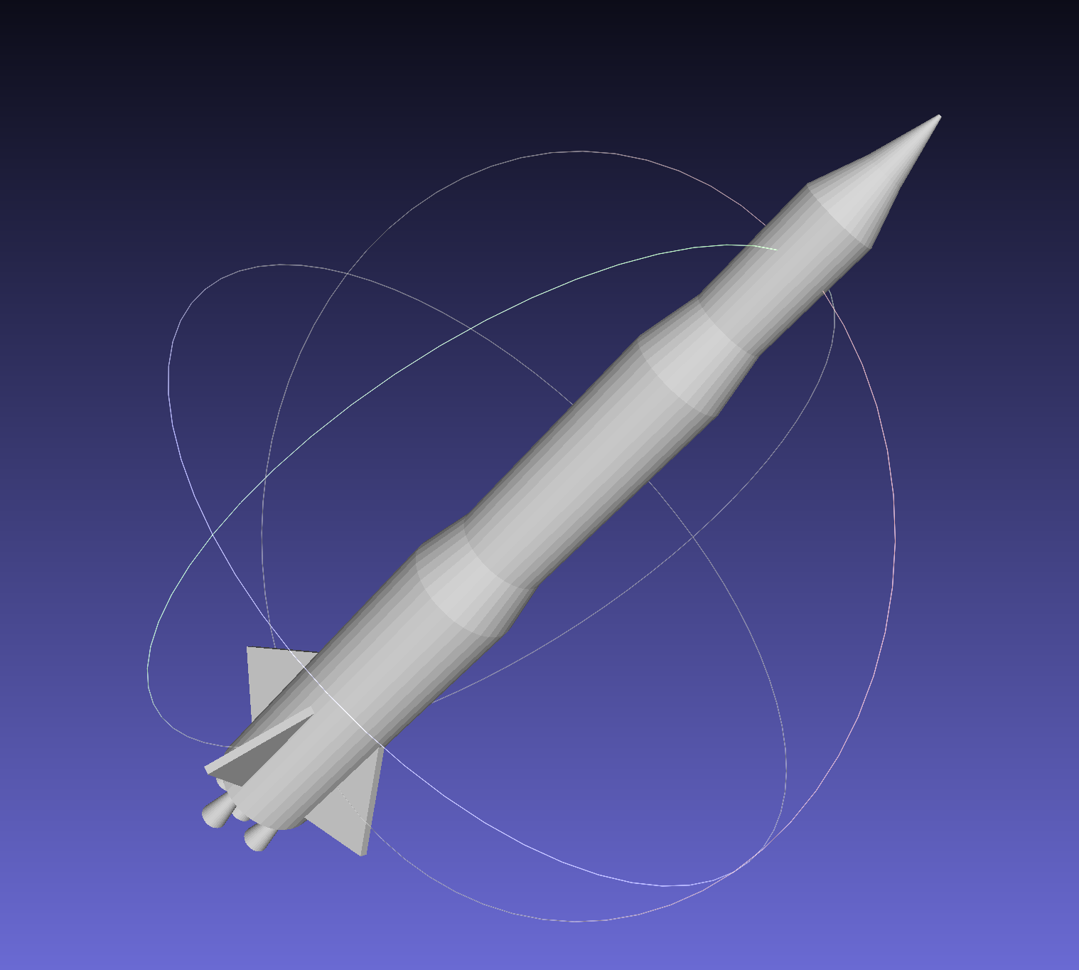
Multi-stage rocket generated with yapCAD and exported to STL.
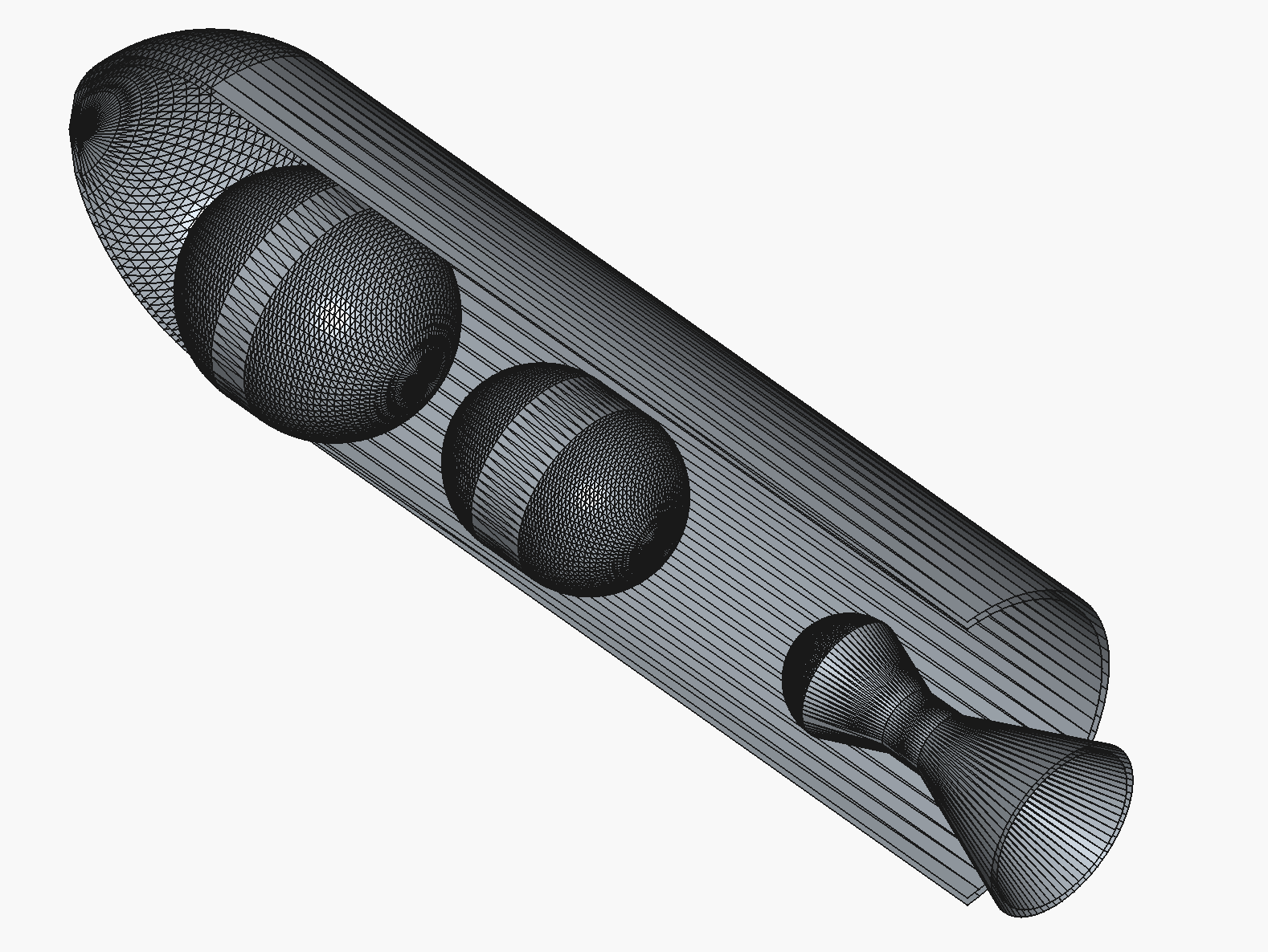
Internal layout from examples/rocket_cutaway_internal.py rendered from
the exported STEP file in FreeCAD.
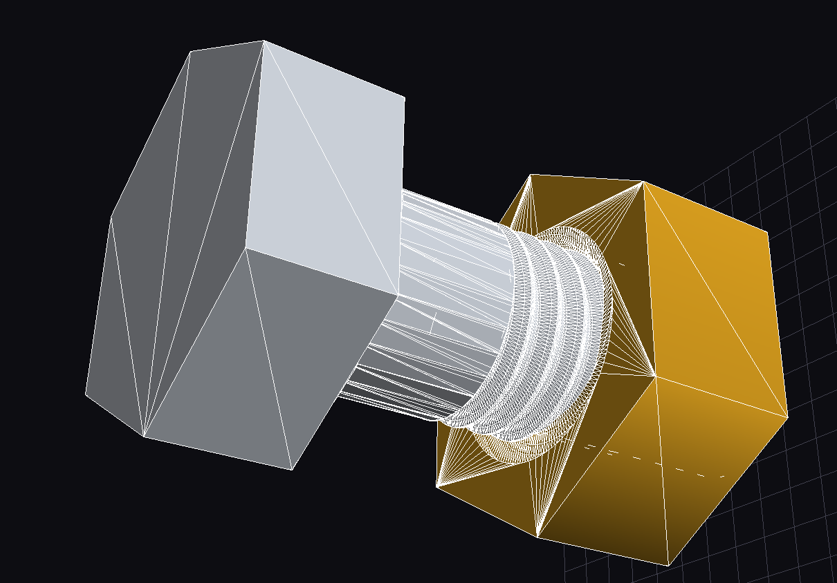
M10 hex-cap screw and nut pair demonstrating yapCAD’s material properties support, rendered with zinc (left) and brass (right) finishes.
Welcome to yapCAD, yet another procedural CAD and computational geometry system, written in Python. Version 1.0 delivers a complete parametric DSL, OCC BREP kernel integration, package signing, validation schemas, and production-ready STL/STEP/DXF export. The reusable .ycpkg package format enables provenance tracking and reproducible designs.
Note
yapCAD was created to solve some fairly specific problems in procedural CAD and parametric design. Earlier releases focused on 2D drawings in AutoCad DXF format; version 1.0 delivers a complete parametric DSL, OCC BREP kernel for exact solid modeling, .ycpkg packaging with signing and validation schemas, and production-ready STL/STEP/DXF export.
Why use yapCAD? yapCAD allows you to transform the 2D and 3D mechanical design process from the manual creation of drawings, parts, and assemblies into a highly automatable process focused creation of modular, parametric, and even LLM-generated code.
Because yapCAD’s foundations are in software, you can use powerful agentic tools to translate your design intent into functional, parameterized code without manual drawing edits. Several shipped examples were authored via LLM prompts to demonstrate automation-friendly workflows.
And becuse yapCAD designs are software, they can be parametric and modular. So if you are tired of manually editing your CAD files whenever you change the thickness of a material, the size of a pipe fitting, or the diameter and spacing of bolts, etc., this might just be the tool you are looking for.
For an example and discussion of what parametric design is and why it might be useful see What is Parametric Design? below.
Much of the documentation for yapCAD can be found in the
README files, as well as in the yapcad.geom module
documentation linked below. Key helper modules include
yapcad.geometry_utils/yapcad.triangulator (triangle
helpers and ear-cut tessellation), yapcad.geometry_checks (mesh
validation), yapcad.metadata (surface/solid provenance),
yapcad.text3d (3D text with TrueType font support and engraving),
yapcad.brep (fillets and chamfers for BREP solids),
yapcad.brep_edge_select (edge selection helpers for selective
fillet/chamfer operations),
yapcad.geom3d_util.stack_solids and cutaway_solid_x (layout and
section tools), yapcad.geom3d_util.helical_extrude (smooth helical
extrusions), yapcad.geom_util.radial_pattern and linear_pattern
(geometry array generation for 2D/3D/solids/surfaces),
yapcad.boolean.native (production-ready boolean engine),
and yapcad.io for validated STL/STEP export.
Contents
- License
- Authors
- Changelog
- Version 1.1.0 (2026-07-05)
- Version 1.0.1 (Development)
- Version 1.0.0rc1 (2025-12-30)
- Version 0.6.3 (2025-12-17)
- Version 0.6.1 (2025-10-30)
- Version 0.6.0 (2025-10-28)
- Version 0.5.1 (2025-10-14)
- Version 0.5.0 (2024-09-30)
- Version 0.4.0 (Development)
- Version 0.3.1
- Version 0.3.0
- Version 0.2.0
- Version 0.1.5
- Module Reference
- yapcad package
- Subpackages
- Submodules
- yapcad.analytic_surfaces module
bspline_surface()bspline_surface_normal()cone_surface()cone_surface_normal()cylinder_surface()cylinder_surface_normal()evaluate_bspline_surface()evaluate_cone_surface()evaluate_cylinder_surface()evaluate_plane_surface()evaluate_sphere_surface()evaluate_surface()evaluate_tessellated_surface()evaluate_torus_surface()is_analytic_surface()is_bspline_surface()is_cone_surface()is_cylinder_surface()is_plane_surface()is_sphere_surface()is_tessellated_surface()is_torus_surface()plane_surface()plane_surface_normal()sphere_surface()sphere_surface_normal()surface_normal()tessellate_surface()tessellated_surface()tessellated_surface_normal()torus_surface()torus_surface_normal()
- yapcad.brep module
- yapcad.brep_edge_select module
edge_info()filter_curved_edges()filter_linear_edges()get_all_edges()intersect_edges()select_bottom_edges()select_edges_at_z()select_edges_by_direction()select_edges_by_length()select_edges_crossing_z()select_edges_in_cylinder()select_edges_in_z_range()select_edges_near_point()select_horizontal_edges()select_top_edges()select_vertical_edges()subtract_edges()union_edges()
- yapcad.combine module
- yapcad.drawable module
- yapcad.ezdxf_drawable module
- yapcad.ezdxf_exporter module
- yapcad.fasteners_legacy module
- yapcad.geom module
- OVERVIEW
- yapcad.geom geometric representations
- yapcad.geom simple (non-compound) figures
- yapcad.geom compound figures
- COMPUTATIONAL GEOMETRY OPERATIONS
add()add4()arc()arcArcIntersectXY()arcbbox()arccenter()arclength()barycentricXY()bbox()bezier()bspline()catmullrom()center()circleCircleTangentsXY()close()cross()dist()dist4()dot()dot4()ellipse()ellipse_bbox()ellipse_length()ellipse_sample()ellipse_tangent()geomlistbbox()homo()hyperbola()hyperbola_bbox()hyperbola_length()hyperbola_sample()hyperbola_tangent()intersectGeomListXY()intersectSimplePolyXY()intersectSimpleXY()intersectXY()isCardinalPlanar()isInsideConvexPolyXY()isInsideTriangleXY()isXYPlanar()isXZPlanar()isYZPlanar()isarc()isbezier()isbspline()iscatmullrom()iscircle()isclosedgeomlist()iscontinuousgeomlist()isdirect()isdirectlist()isellipse()isfullellipse()isgeomlist()isgeomlistXYPlanar()isgoodnum()ishyperbola()isinsideXY()isinsidearcXY()isinsidebbox()isinsidebbox2D()isinsidegeomlistXY()isinsidelineXY()isinsidepointXY()isinsidepolyXY()isline()isnurbs()isparabola()ispoint()ispoly()ispolygon()ispolygonXY()issimple()istriangle()isvect()length()line()lineArcIntersectXY()lineLineIntersectXY()linePointXY()linePointXYDist()linebbox()linecenter()linelength()mag()mag4()mirror()mul()mul4()nurbs()orthoXY()parabola()parabola_bbox()parabola_length()parabola_sample()parabola_tangent()point()pointCircleTangentsXY()pointbbox()pointcenter()pointlength()poly()polybbox()polycenter()polylength()reverseGeomList()rotate()sample()samplearc()samplegeomlist()sampleline()samplepoint()samplepoly()scale()scale3()scale4()segment()segmentarc()segmentgeomlist()segmentline()segmentpoly()sub()sub4()transform()translate()unsample()unsamplearc()unsamplegeomlist()unsampleline()unsamplepoly()vclose()vect()vstr()
- yapcad.geom3d module
addTri2Surface()bbox()center()issolid()issolidclosed()issurface()linePlaneIntersect()mirror()mirrorsolid()mirrorsurface()normfunc()poly2surface()poly2surfaceXY()reversesurface()rotate()rotatesolid()rotatesurface()scale()scalesolid()scalesurface()signedFaceDistance()signedPlaneDistance()solid()solid_boolean()solidbbox()solids_intersect()surf2lines()surface()surfacearea()surfacebbox()translate()translatesolid()translatesurface()tri2p0n()triTriIntersect()volumeof()
- yapcad.geom3d_util module
adaptive_angr_from_radius()adaptive_arc_segments()addVertex()circleSurface()conic()conic_tube()contour()dodecahedron()extrude()extrude_region2d()helical_extrude()linear_pattern_solid()linear_pattern_surface()loft()makeIcoPoints()makeLoftSolid()makeRevolutionSolid()makeRevolutionSurface()makeRevolutionThetaSamplingSurface()make_occ_helix()oblate_spheroid()prism()radial_pattern_solid()radial_pattern_surface()rectangularPlane()sphere()sphere2cartesian()sphereSurface()spherical_shell()stack_solids()subdivide()sweep_adaptive()sweep_along_path()sweep_profile_along_path()tube()
- yapcad.geom_util module
- yapcad.geometry module
- yapcad.geometry_checks module
- yapcad.geometry_utils module
- yapcad.mesh module
- yapcad.metadata module
add_analysis_record()add_bolt_pattern()add_compliance()add_datum()add_design_history_entry()add_keepout()add_surface()add_tags()ensure_solid_id()ensure_surface_id()get_assembly_metadata()get_operation_metadata()get_solid_metadata()get_surface_metadata()set_assembly()set_envelope_constraint()set_layer()set_manufacturing()set_mass_constraint()set_material()set_operation()set_solid_context()set_solid_metadata()set_surface_metadata()set_surface_origin()set_surface_units()
- yapcad.native_brep module
ShellClosureErrorSolidValidationErrorTopologyGrapharc_edge()attach_native_brep_to_solid()brep_edge()brep_face()brep_loop()brep_shell()brep_solid()brep_trim()brep_vertex()bspline_edge()circle_edge()clear_native_brep()deserialize_topology_graph()edge_curve_params()edge_curve_type()edge_id()edge_vertices()evaluate_edge_curve()face_id()face_loops()face_surface()has_native_brep()is_brep_edge()is_brep_face()is_brep_loop()is_brep_shell()is_brep_solid_native()is_brep_trim()is_brep_vertex()line_edge()loop_id()loop_trims()loop_type()mirror_native_brep()native_brep_from_solid()rotate_native_brep()scale_native_brep()serialize_topology_graph()set_shell_closed()set_vertex_location()shell_closed()shell_faces()shell_id()solid_id()solid_shells()transform_edge_params()transform_topology_graph()translate_native_brep()trim_edge_id()trim_id()vertex_id()vertex_location()vertices_coincident()
- yapcad.occ_native_convert module
- yapcad.octtree module
- yapcad.poly module
- yapcad.pyglet_drawable module
- yapcad.spline module
- yapcad.text3d module
- yapcad.threadgen module
- yapcad.triangulator module
- yapcad.xform module
- Module contents
- yapcad package
- README
- Roadmap
- DSL Language Guide
- 1. What the yapCAD DSL is (and why it exists)
- 2. The execution model
- 3. Modules, commands, and the UPPERCASE/lowercase rule
- 4. Thinking in types
- 5. Control flow — and the deliberate omissions
- 6. Composing geometry: the core workflow
- 7. Idioms, conventions, and gotchas
- 8. Annotating for tooling:
@metaand@ui - 9. From source to artifact: the CLI loop
- 10. Where to go next
- DSL Tutorial
- DSL Reference
- Quick Start
- CLI Usage
- Syntax Overview
- Module Structure
- Parameter Decorators
- Types
- Built-in Functions
- Math Functions
- Point and Vector Constructors
- 2D Shape Constructors
- Curve Constructors
- Curve Sampling Functions
- Path Constructors
- 2D Boolean Operations
- Solid Constructors
- Solid from 2D Operations
- Boolean Operations
- Edge Finishing and Selection
- Transformation Functions
- Pattern Functions
- Text Functions
- Path and Manufacturing Utilities
- Query Functions
- List Functions
- Aggregation Functions
- Utility Functions
- Method Syntax
- Statements
- Common Patterns
- Type System Notes
- Error Messages
- Package Integration
- Programmatic API
- Static Verifiability and Safety
- See Also
- BREP Implementation
- Assembly System
- Manufacturing Post-Processing
- Project Packaging
- Geometry JSON Schema
- Metadata Namespace
- Validation Schema
- Package Signing
- Material Schema
- Mesh Validation
Indices and tables
What is Parametric Design?
Parametric design is a generalizable approach to solving design problems by means of parameters and algorithms, as opposed to the creation of static drawings or models. Put another way, a conventional design is like a drawing, and a parametric design is like a piece of software that you configure to create the specific drawing that you want.
the acrylic box: a parametric design example
For example, imagine that you wanted to design a decorative acrylic box to be assembled from pieces cut from a sheet of material of uniform thickness. This box will be a squeeze-fit design, so that it assembles like a 3D jigsaw puzzle, without the need for additional glue or fasteners.

You might decide on the dimensions of your box, and a scheme by which you cut the edges to create tabs and slots so that when cut, the box will fit together just so. However, the depth of your tabs and slots will necessarily depend on the thickness of the material, which might vary slightly from sheet to sheet, or vendor to vendor. Furthermore, your cutting tool (perhaps a laser cutter) will create a kerf, or width of cut, that vary from machine to machine and with depth of focus.
Finally, your box might be sized to hold a variety of contents, which themselves might vary in size and shape.
One approach is to create a conventional design. You could draw your design for one size of box, material, and thickness of cut, and then hope you have your tolerances correct. If there is a problem, or you want to change box dimensions, you will need to go back and revise your design. Each time you revise, you are essentially redoing the entire drawing from scratch.
Alternately, you could create a parametric design, in which the desired length, width, and height of the box are input parameters, along with the thickness of the material and an estimate of the kerf. Creating a parametric design system might be a bit more difficult than creating a conventional drawing, but once you are done you will be able to generate the design for any desired box, from any desired material thickness, with any kerf, simply by changing a few numbers – automatically, and without having to revise any code or drawing.
Note
- For a yapCAD solution to this particular problem, see the
boxcutexample in theexamplesdirectory for a 2D parametric workflow, androcket_demo.pyfor a 3D generative workflow that visualises and exports STL.
Generative fasteners
The yapcad.fasteners helpers provide canonically parameterized screws, nuts, and washers for both metric and unified standards. They build on the thread sampler developed for the involute gear work and support external/internal threads, handedness, multi-start configurations, and catalog-backed defaults. See examples/threaded_fastener_package.py for a CLI that emits .ycpkg packages for common fasteners, or consume the helpers directly from Python/DSL to populate assemblies.
This ability to solve for an entire family of related design problems with a single parametric design system is what gives this approach it’s power and flexibility. For anyone who has spent hours re-drafting a drawing to accommodate minor variations in requirements, this can be an impressive force multiplier on productivity.